How does wind resistance affect high mast street light poles? The answer begins with exposure, geometry, and time. A 25-meter pole presents a long lever arm to gusts. Its upper luminaire can behave like a small sail, especially when mounted beside open highways or coastal roads.
ASCE/SEI 7-22 evaluates wind using three-second gust speeds, exposure categories, directionality, topography, and structural importance. These factors can change the design pressure significantly. The AASHTO LRFD Specifications for Structural Supports also address wind loading, fatigue, vibration, and connection behavior for highway lighting structures. NCHRP Report 469 warns that repeated wind effects can contribute to fatigue damage, even when a pole survives one severe storm. That distinction matters.
Very few failures begin dramatically.
They often begin with movement.
Wind resistance affects pole diameter, wall thickness, foundation depth, anchor bolts, and luminaire connections. It also influences deflection, vortex shedding, and long-term fatigue. Dr. Peter A. Irwin, a recognized wind-engineering specialist, emphasizes: “Wind must be treated as a dynamic action, not merely a pressure value.” His point remains practical at site level. A pole may meet a basic pressure calculation yet perform poorly under repeated gust cycles.
Real projects are messier than drawings. Nearby buildings can create turbulence. Salt air can reduce connection reliability. Maintenance access can alter equipment weight. Engineers should verify local wind maps, soil conditions, corrosion exposure, and manufacturer test data before approval. This guide examines seven practical ways wind resistance shapes high mast street light pole safety, durability, and cost. One uncomfortable lesson remains: a neat calculation is not always the whole truth.
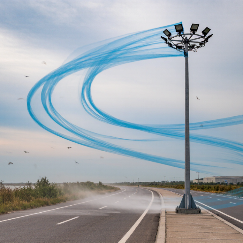
7 Tips How Wind Resistance Affects High Mast Street Light Poles?
Wind Load Design Basis: 3-Second Gusts, Exposure, and Return Periods
Design begins with wind speed, not an annual average. A three-second gust captures a sharp pressure peak that an average wind can hide. Local structural codes define the reference speed, measurement height, and adjustment factors. Use the governing standard for the project location. Do not guess. A return period describes statistical probability, not a guaranteed storm interval. A 50-year event can occur tomorrow.
Exposure describes the surrounding terrain. Open coastal land, farmland, and dense urban streets produce different wind pressures. Nearby buildings may provide temporary shielding, but future development can remove it. High mast poles also experience stronger forces with height. Calculate pressure at relevant elevations, including topographic speed-up. Check the pole’s taper, projected area, steel grade, connections, and dynamic response.
Field inspections often reveal overlooked accessories. Large luminaires, banners, ladders, and internal cables add drag area. Evaluate vortex shedding, fatigue, and deflection, not strength alone. Foundation reactions must match the soil report and anchor design. A neat spreadsheet can still hide a bad assumption. Recheck calculations against site photographs, construction tolerances, and maintenance loads. Independent engineering review can catch an incorrect exposure category or return period before concrete is poured. Wind is uneven.
Estimated velocity pressure increases with height because wind exposure becomes more severe above the ground. This screening chart uses a 3-second gust wind speed of 40 m/s, a directionality factor of 0.85, and representative exposure coefficients for open terrain. Final pole design should use the governing regional wind map, terrain category, importance level, and required return period.
The plotted pressure is based on the SI relationship qz = 0.613V²KzKd. Exposure B represents suburban terrain, Exposure C represents open terrain, and Exposure D represents flat unobstructed terrain. Higher pressure increases the required pole diameter, wall thickness, foundation capacity, and connection strength. Three-second gust speeds are commonly paired with code-defined return periods, such as 50 years or longer for critical infrastructure.
Wind resistance begins with projected area, not pole weight. For a circular high mast pole, engineers usually calculate the exposed area as diameter multiplied by height. A 12-meter pole with a 0.30-meter diameter presents about 3.6 square meters of shaft area.
The key equation is F = 0.5ρV²CdA. For a smooth circular cylinder, Cd is commonly taken as approximately 1.2 in preliminary design. This value reflects separated airflow around the curved surface. At 40 m/s wind speed, using air density of 1.225 kg/m³, the example pole experiences roughly 4.2 kN of drag force. That force acts across the projected area. Small changes matter.
ASCE 7-22 uses velocity pressure based on wind speed, exposure, height, and directionality factors. EN 1991-1-4 also requires designers to consider turbulence and external pressure coefficients. AASHTO’s structural support guidance adds practical checks for luminaires, brackets, access doors, and other attachments. These components may create more projected area than expected. Field inspections often reveal loose fixtures or surface damage, which can increase uncertainty. The Cd ≈ 1.2 assumption is useful, but imperfect. Reynolds number, pole roughness, nearby buildings, and wind angle can change actual loading. Engineers should verify the complete assembly, including foundation reactions and fatigue effects, rather than checking the shaft alone.
High mast poles respond to wind in two different ways: gust loading and vortex shedding. ASCE 7-22 defines basic wind speed through a three-second gust, not a steady wind average. This distinction matters because short gusts can create sharp changes in pole bending and foundation reactions. EN 1991-1-4 uses a different reference approach, based largely on ten-minute mean wind speeds. Engineers must not mix these values casually.
Vortex shedding creates alternating pressure on the pole. For a circular shaft, the Strouhal number is commonly near 0.2. The shedding frequency can be estimated as f = StV/D, where V is wind speed and D is pole diameter. If that frequency approaches the pole’s natural frequency, vibration may increase rapidly. Damping, taper, mounted equipment, and cable movement can change the response. Small differences matter.
Field inspections often reveal loose access doors, worn dampers, or unexpected luminaire movement. These details are easy to overlook. A spreadsheet may look precise, yet its assumptions can remain weak. The National Cooperative Highway Research Program Report 469 emphasizes fatigue and wind-sensitive details in support structures. Designers should check both static strength and repeated stress cycles. Site terrain, exposure category, and local gust records deserve direct verification. Wind tunnel testing may be sensible for unusually tall or heavily equipped poles. Not every project needs it. Some projects probably need it earlier than expected.
Wind resistance can govern a high mast street light pole before its weight becomes critical. Gust pressure acts on the shaft, outreach arms, luminaires, cables, and maintenance equipment. The combined force creates bending stress at the base connection. Engineers should verify wind speed, exposure, drag coefficients, and gust effects using the applicable local design standard.
Tip 1: Check stress at every critical section. Include welds, access doors, flange plates, anchor bolts, and arm connections. A small door opening can create local stress concentration. Deflection also matters. Excessive movement may disturb lighting coverage, loosen fittings, or alarm nearby traffic. Field inspections often reveal vibration that a simple static calculation misses.
Tip 2: Verify buckling under combined compression and bending. Thin tapered shafts can appear strong but lose stability after local yielding. Review effective length, imperfections, residual welding stresses, and connection stiffness.
Tip 3: Assess fatigue from repeated gusts and vibration. Wind does not need to exceed the ultimate design value to cause damage. Stress ranges near weld toes deserve careful attention. A rainwater seal or cable opening may also become a fatigue detail. Engineers should compare calculated results with material certificates, fabrication records, and inspection findings. No model is perfect; assumptions should be documented, challenged, and revised when site evidence disagrees.
Wind resistance controls more than pole selection. It also governs foundation depth, anchor strength, and inspection frequency. ASCE 7-22 requires designers to consider wind speed, exposure, topography, and projected area. These inputs directly influence the pole’s base moment.
Use the site’s basic wind speed, not a convenient regional average. Check luminaire area, access doors, banners, and cable openings. Small attachments can create surprising torsional effects. AASHTO’s LRFD Specifications recommend evaluating fatigue, deflection, and foundation interaction for roadside structures. The concrete footing should resist overturning, sliding, and soil rotation. Anchor rods need adequate embedment, edge distance, and pretension. Poor leveling can concentrate stress under the base plate.
Keep water away from the foundation. Grade soil outward, seal cable entries, and inspect grout for cracks. Corrosion deserves equal attention. The NACE IMPACT study estimated global corrosion costs near 3.4% of worldwide GDP, showing why protective maintenance is not cosmetic. Inspect the lower shaft, welds, base plate, nuts, and anchor threads after severe storms. Measure section loss when rust appears; visual judgment alone can be misleading.
That mistake happens.
Torque records should match the engineer’s specification. Recheck plumbness and foundation cracking annually, then reassess after unusual wind events. Galvanizing can delay corrosion, but damaged coatings still need repair. In practice, maintenance schedules are often too optimistic. Local drainage, salt exposure, and construction damage can change the risk faster than expected.
It captures a sharp pressure peak that annual average wind speeds can hide. Short gusts matter.
It describes statistical probability, not a guaranteed waiting time. A fifty-year event can happen tomorrow.
Open farmland, coastal areas, and dense streets create different wind pressures. Nearby buildings may shield a pole temporarily. Future construction can remove that protection.
Wind usually becomes stronger with elevation. Designers should check pressure at relevant heights and consider local speed-up effects.
Check the tapered shaft, luminaires, arms, cables, doors, ladders, and maintenance equipment. Small accessories can add surprising drag.
Wind can create alternating pressure behind a circular pole. The resulting vibration may increase when shedding frequency approaches the pole’s natural frequency.
Review damping, taper, equipment movement, cable behavior, and natural frequency. Loose doors and worn dampers deserve attention. Small details matter.
Check stress, deflection, buckling, connection strength, and fatigue. A pole may pass strength checks yet vibrate excessively or fatigue near welds.
Door openings and weld toes can concentrate stress. Anchor bolts and flange plates must transfer foundation reactions safely. Neat drawings can still hide weak assumptions.
Use independent review when exposure, height, equipment, or site conditions are uncertain. Wind testing may help unusually tall or heavily equipped poles. Not every project needs it, but some need it earlier.
Wind resistance is a key factor in the safety, durability, and performance of high mast street light poles. The question “how does wind resistance affect high mast street light poles” begins with the design wind load, which is commonly based on 3-second gust speeds, site exposure, and the expected return period. Engineers calculate the projected area of the pole, fixtures, and accessories, while considering the drag coefficient of a circular pole, typically around 1.2. These values determine the total wind force and the base moment transferred to the foundation.
Wind can also create dynamic effects through gust response and vortex shedding, so the pole must be checked for vibration and fatigue. Structural verification should include stress, top deflection, buckling resistance, and repeated-load performance. A properly designed foundation, suitable anchor system, and regular maintenance help control movement, protect connections, and prevent corrosion. Together, these measures ensure that high mast street light poles remain stable and reliable throughout their service life.
